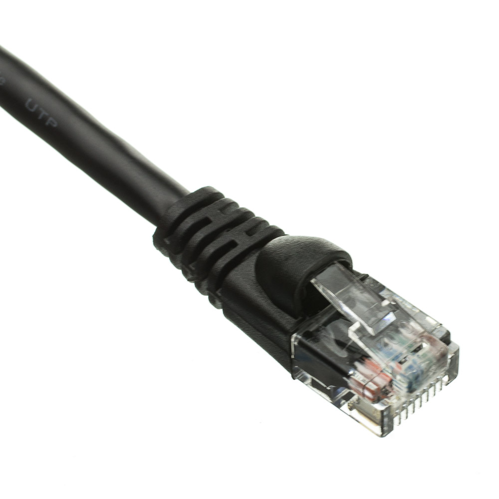
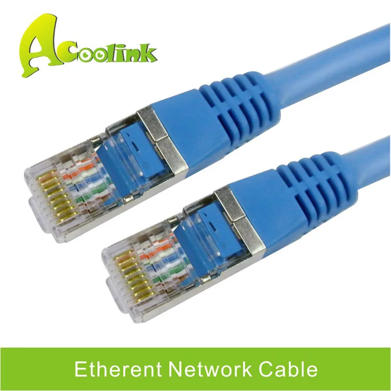
A patch cable, patch cord or patch lead is an electrical or optical cable used to connect ('patch in') one electronic or optical device to another for signal routing. Devices of different types (e.g., a switch connected to a computer, or a switch to a router) are connected with patch cords.
Patch cords are usually produced in many different colors so as to be easily distinguishable from each other. Types of patch cords include microphone cables, fiber optic spectroscopy cables, headphone extension cables, XLR connector, Tiny Telephone (TT) connector, RCA connector and ¼' TRS phone connector cables (as well as modularEthernet cables), and thicker, hose-like cords (snake cable) used to carry video or amplified signals. However, patch cords typically refer only to short cords used with patch panels.
The term 'patch' came from early use in telephony and radio studios, where extra equipment kept on standby could be temporarily substituted for failed devices.[citation needed] This reconnection was done via patch cords and patch panels, like the jack fields of cord-type telephone switchboards. Furthermore, patching could also create temporary atypical connections between devices for unusual needs. Analog music synthesizers typically use patch cables to interconnect functional sections, such as oscillators, filters, etc.

A patch cord cable differs from a standard structured cabling in that a patch cable is stranded for flexibility, whereas a standard cable is solid copper. Because the patch cord is stranded copper construction the attenuation (signal loss) is higher on patch cords than solid cable so short lengths should be adhered to.[1]
They can be as short as 3 inches (c. 8 cm), to connect stacked components or route signals through a patch bay, or between 6 meters (c. 20 feet) and 50 meters (c. 164 feet) for snake cables. As length increases, the cables are thicker or more shielded, or both, to prevent signal loss (attenuation) and the introduction of unwanted radio frequencies and hum (electromagnetic interference).
Patch cords are often made of coaxial cables, with the signal carried through a shielded core, and the electrical ground or earthed return connection carried through a wire mesh surrounding the core. Each end of the cable is attached to a connector so that the cord may be plugged in. Connector types may vary widely, particularly with adapting cables.
Patch cords may be:
- single-conductor wires using, for example, banana connectors (or pin plugs)
- coaxial cables using, for example, BNC connectors
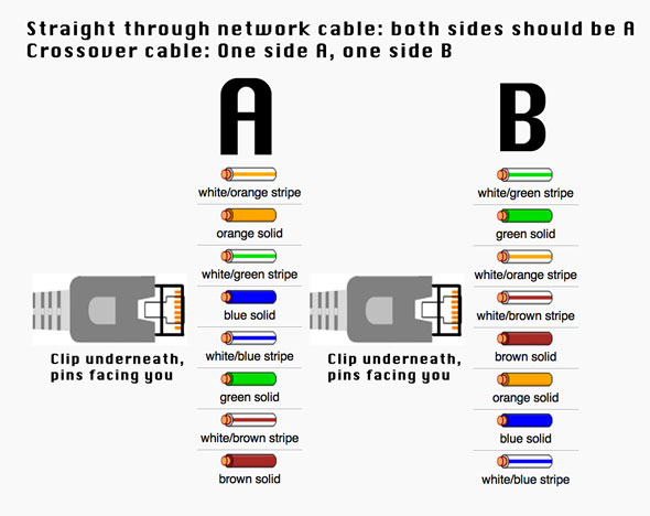
- shielded or unshielded Cat5, Cat5e, Cat6 or Cat6A cables using 8P8C (RJ-45) modular connectors with straight-through T568A or T568B wiring (modular cables wired to T568A at one end and T568B on the other are more commonly referred to as crossover cables)
- qualifiedoptical fiber cables for use with modular fiber optic spectroscopy equipment

A patch cord is always fitted with connectors at both ends. A pigtail is similar to a patch cord and is the informal name given to a cable fitted with a connector at one end and bare wires (or bare fibre) at the other. In the context of copper cabling, these cables are sometimes referred to as blunt patch cords and the non-connectorized end ('the pigtail') is intended to be permanently attached to a component or terminal. Optical fiber pigtails, in contrast to copper pigtails, can be more accurately described as a connector than a cable or cord. A fiber pigtail is a single, short, usually tight-buffered, optical fiber that has an optical connector pre-installed on one end and a length of exposed fiber at the other end. The end of the fiber pigtail is stripped and fusion spliced to a single fiber of a multi-fiber trunk. Splicing of pigtails to each fiber in the trunk 'breaks out' the multi-fiber cable into its component fibers for connection to the end equipment.[2]
UTP Cabling Pinouts Wiring. Connectors are frequently terminated using the T568A or T568B pin/pair assignments that are defined in TIA/EIA-568-B. The drawings to the right show that the copper connections and pairing are the same, the only difference is that the orange and green pairs (colors) are swapped. (“Patch cable”) connection. Pinout of Power over Ethernet (POE) and layout of 8 pin RJ45 (8P8C) female connector and 8 pin RJ45 (8P8C) male connectorPower over Ethernet is a technology that allows IP telephones, wireless LAN Access Points, security network cameras and other IP-based terminals to receive power, in parallel to data, over the existing CAT-5 Ethernet infrastructure without the need to make any modifications. Controversies and Caveats: Category 5, 5E, and Cat 6 Patch Cables 568B vs. 568A For patch cables, 568-B wiring is by far, the most common wiring method. Virtually all pre-assembled patch cables are wired to the B standard. There is no difference in connectivity between 568B and 568A cables. Therefore, a 568B patch cable should work fine on a. Modular, RJ-45, straight-through UTP cable to connect the management port to an external hub, switch, or router. Figure 5-3 lists the cable pinouts for 10/100/1000BASE-T management port cable pinouts (MDI/MDIX). Figure 5-3 10/100/1000 BASE-T Management Port Cable Pinouts (MDI/MDIX) Console and Auxiliary Ports (RJ-45) Figure 5-4 shows the RJ 45. Ethernet Cable, 6 Feet (5 Pack) Cat 6 High Speed LAN, Utp, RJ45, Network, Cat6 Internet Cord – Pure Copper, UL Listed – Multi, 6ft. (5-Pack) 4.6 out of 5 stars 186.

Music and sound recording[edit]

A variety of cables are used to carry electrical signals in sound recording studios and with electronic or electrical musical instruments. Microphones are typically connected to mixing boards or PA systems with XLR microphone cables which use three-pin XLR connectors. A huge range of electric or electronic instruments use 1/4 inch mono patch cords to connect the instrument to the amplifier, such as the electric guitar, electric bass, synthesizer, electric piano, or electronic drum machine. Musicians playing electric or electronic instruments often use longer cables (from 10 to 20 feet) between their instrument and their amplifier, and then use shorter patch cords (from a few inches to one or two feet long) to connect chains of effects devices, 'stomp box' pedals, or other signal processors.
DJs using record players connect their turntables to mixers or PA systems with stereo RCA connectors. DJs sometimes have to use equipment with multiple cable types, which can create connection difficulties; for example, the DJ's record players and DJ mixers all use RCA connectors, but if they use a drum machine or a bass synthesizer, it may have a 1/4 inch mono connector. To resolve this problem, DJs can either use adapters or special cables (e.g., RCA to 1/4 inch mono). Heavier-gauge cables are used for carrying amplified signals from amplifiers to speakers (both in a PA system and with instrument amplifiers). ¼' TRS phone connector cables can carry stereo signals, so they are used for stereo headphones and for some patching purposes (e.g., inserting an effect into an insert connection in a mixer).
Music venues, concert halls, and recording studios also use a thicker, hose-like cord called a snake cable (or a 'snake'), which consists of a bundle of many individual cables with patch bays at either end so that audio gear can be connected. The patch bay is a flat panel of audio connectors where XLR cables (often both 'male' and 'female') and 1/4 inch jacks can be plugged in. The 'snake' cable makes setup more convenient, because if a sound engineer did not have a 'snake', she or he would have to run 20 or 30 individual microphone and instrument cables from the stage to the mixing booth. The cables could get tangled or mixed up, and it would be hard to know, when faced with 20 connectors at the end of the cable run, which cable was associated with which microphone or instrument. The patch bay is numbered, so that the engineer can note which microphone or instrument is plugged into each numbered connection.
Patch cables can also be used on video synthesizers.
See also[edit]
References[edit]

- ^'Data Cabling FAQs'. Cabling Solutions. Retrieved 2015-11-10.
- ^'Pigtail'. www.atis.org. ATIS Telecom Glossary. Retrieved 3 September 2014.